| Sign In | Join Free | My frbiz.com |
|
| Sign In | Join Free | My frbiz.com |
|
| Categories | Cable Sheath Fault Locator |
|---|---|
| Brand Name: | XZH TEST |
| Model Number: | XHHD523L |
| Certification: | CE |
| Place of Origin: | Xi'an, Shaanxi, China |
| MOQ: | 1 unit |
| Price: | EXW 2500 |
| Payment Terms: | T/T |
| Supply Ability: | 500 units/month |
| Delivery Time: | 5-8 work days |
| Packaging Details: | Wooden case |
| Input voltage: | 220V (±10%), 50Hz (±2Hz) |
| Output voltage: | 0 ~ 10kV (square wave) adjustable |
| Output curren: | 0~200mA |
| Output capacity: | 2kVA |
| Color: | Black |
| Gross weight: | 48kg |
| Package dimension: | 64*42*70cm |
| Company Info. |
| Xi'an Xu&Hui Electromechanical Technology Co., Ltd. |
| Verified Supplier |
| View Contact Details |
| Product List |
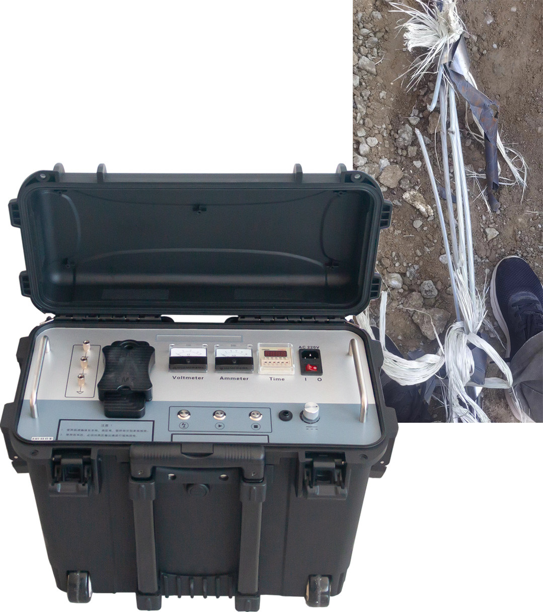
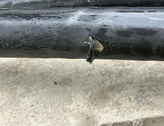
The output voltage of the high-voltage cable outer sheath fault detector is 10KV and below, which fully meets the Chinese national standard GB50150-2006 cable outer sheath withstand voltage test regulations, including the cable outer sheath handover We test and preventive test suitable for cross-interconnect systems And the fault location of the outer sheath of the cable. Quickly and accurately find hidden dangers of 10kv-500kv single-core and three-core high-voltage and ultra-high voltage cable outer sheath grounding faults and large leakage currents. At the same time, it can perform 5kv-10kv on high-density polyethylene and polyvinyl chloride cable outer sheaths, 1 The minute DC withstand voltage test is a special instrument necessary for the maintenance of cable equipment of 10kv-500kv single-core and three-core high-voltage and ultra-high voltage cable operation units, ultra-high voltage cable engineering companies, and various power transmission and transformation engineering companies.
Main features
Technical data
1 Input voltage: 220V (±10%), 50Hz (±2Hz);
2 Output voltage: 0 ~ 10kV (square wave) adjustable;
3 Output current: 0~200mA;
4 Output capacity: 2kVA;
5 Frequency adjustment: Min: 0.2Hz, Max: 5Hz (range adjustable).
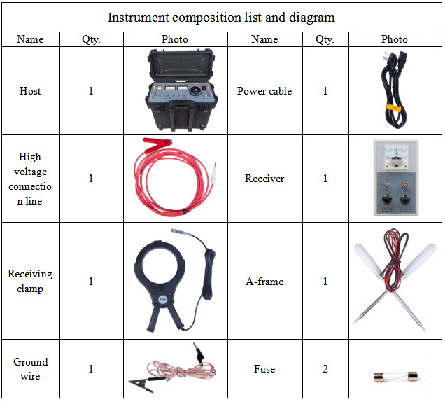
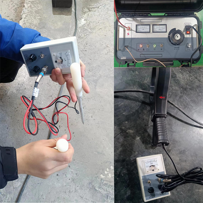
Composition of the instrument
1 Cable outer sheath fault locator: a unit for fault location or withstand voltage test;
2 High-voltage connecting line: connect the high-voltage output end of the host and the cable core under test;
3 Power cord: the working power cord of the instrument;
4 Receiver: the unit that receives the signal when the fault is located;
5 fuse: 8A fuse is used, AC220V power supply system backup fuse;
6 Ground wire: instrument ground wire;
7 Receiver clamp: clamp receiver;
8 A sub-rack: used in the step voltage method.
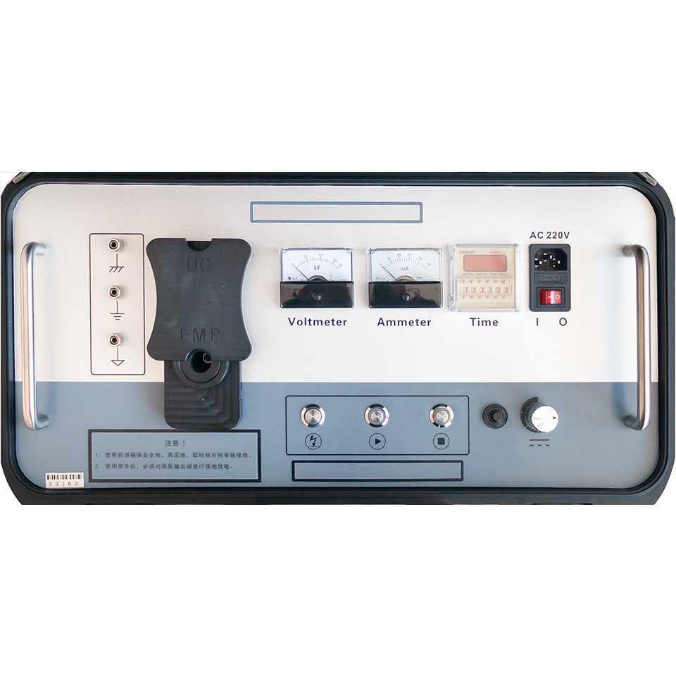
Operation interface introduction

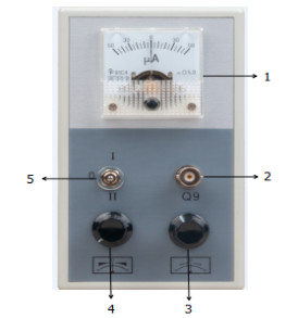
1. Micro-ampere meter: indicates the magnitude and direction of the signal
2. Signal: The input interface of the signal is used to connect the A-frame or the receiving clamp;
3. Zero adjustment: the reference base of the adjustment signal in the "Ⅰ" mode; it does not work in the "Ⅱ" mode;
4. Adjustment: adjust the amplitude of the input signal;
5. Gear switch: "0" gear means shutdown state;
"Ⅰ" file can be used in step voltage test mode and receiving clamp test mode;
It is suitable for the test environment with weak input signal (with amplifying circuit inside);
“Ⅱ” gear can only be used in step voltage test mode;
It is suitable for test environment with strong input signal (no amplifier circuit inside);
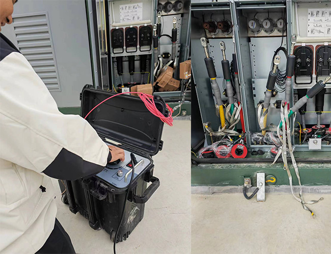
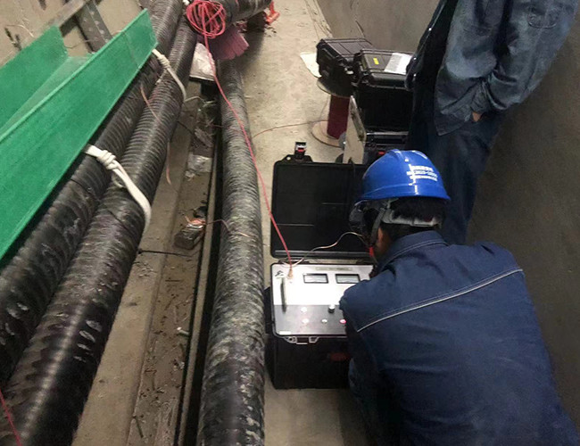
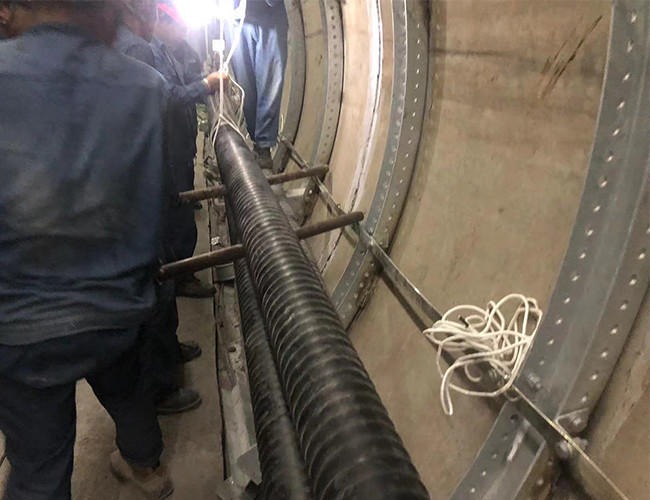
Onsite test

|
