This cable pipe locator XHGX507X uses the electromagnetic field
signal of the underground cable to locate the cable, and gives the
depth and current readings, so as to realize the cable detection
function.
The transmitter and receiver of this device comply with Part 15 of
the U.S. FCC Rules, this equipment complies with the relevant
provisions of European Directive 1999/5/EC.Features:This device can be used for cable path search, power unlive and
live cable identification
Supports current direction and phase indication functions, and has
a unique technology that can display the current direction and
phase of the tracking signal, effectively improving the accuracy of
the search path.
At the same time, it can also detect the buried depth of the cable.
Transmitter with multiple frequency options, 577HZ,
815HZ,8KHZ,33KHZ, 65KHZ,82KHZ,133KHZ,SS LOW, SS HIGH,
Multi-frequency mode.
Function with ohmmeter to test current external continuous
resistance value.
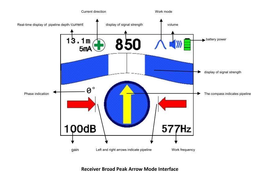
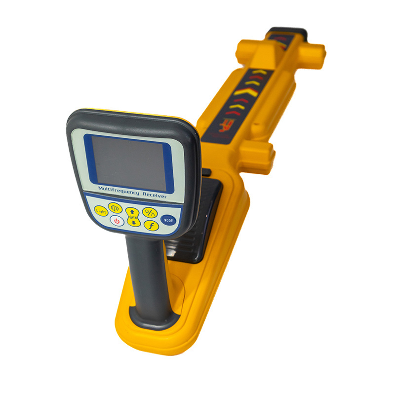
Digital display of signal strength
Left and right arrows indicate pipeline location
Working frequency
Graphical display of signal strength
Operating mode
Battery power
The compass indicates the direction of the pipeline
Real-time display of pipeline depth and current
Brief introduction to the transmitter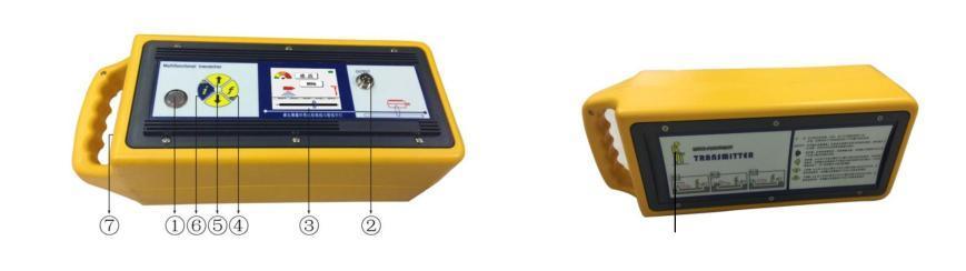 Transmitter instrument panel and function introductionThe transmitter is a signal source that can emit enough power, and
is one of the cores of this set of instruments. It has complete
functions, high intelligence and simple operation.Panel Introduction
Transmitter instrument panel and function introductionThe transmitter is a signal source that can emit enough power, and
is one of the cores of this set of instruments. It has complete
functions, high intelligence and simple operation.Panel Introduction
Note: see the picture above
1. Key 2. Output port 3. LCD display area 4. Frequency compound key
5. Power adjustment
compound key
6. Menu composite key 7. Charging port
Function introduction
1. Switch key: This switch is a self-locking switch; press it to
turn on the power, the transmitter is in working state; pop up to
disconnect the power supply, the transmitter is in a shutdown
state.
2. Output port: This port is a multi-core dedicated aviation
socket; it is used to change the output mode of the signal.
Connecting the direct connection line is the direct connection
mode; inserting the coupling clamp connection is the coupling mode;
not connecting the line is the induction mode.
3. Liquid crystal display area: Display the required basic
information.
4. Frequency key: This key is a jog soft switch; the frequency of
the output signal can be changed every time it is pressed; the
initial power-on is 577Hz. Initially 8KHz in sensing mode. In the
frequency setting menu interface, press this key to select or
cancel the frequency covered by the light bar; in the
multi-frequency mode setting, press this key to choose to replace
the output frequency channel.
5. Power key: This key is a jog soft switch; the output power can
be changed once every time it is pressed, and it can be selected
from low-grade, mid-grade, high-grade and full-grade. Flip through
the frequency menu; in multi-frequency mode setting, press this key
to select the output frequency.
6. Menu key: This key is a jog soft switch; press this key to cycle
into the frequency setting menu, resistance measurement mode, and
multi-frequency mode setting.
7. Charging port: This port is a Φ2.1 charging stand; it is used to
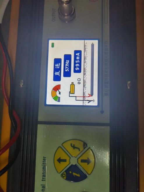
connect a special charger to charge the battery.Transmitter interface display content| Frequency | Display the current output frequency |
| Power | Display the current output power; it can display low-grade,
mid-grade,
high-grade and full-grade respectively |
| Mode | Displays the current working mode; direct connection, coupling, and
induction can
be displayed separately. |
| Current | Display the current loop current value; the effective display is
0-999 mA.
Impedance: Display the current loop impedance value; the effective
display is
00001-20000 ohms. |
| Power | Indicates the current battery power; it is represented by a battery
symbol, all black is
full power, and the left is the current power percentage display. |
| Matching tip | When the circle below the picture starts to roll, it means that the
transmitter is
working stably. |
| Frequency setting | 577Hz, 815Hz, 8kHz, 33kHz, 65kHz, 82kHz, 133kHz, ss low, ss high,
multi-frequency mode. |
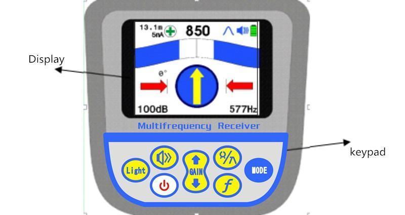
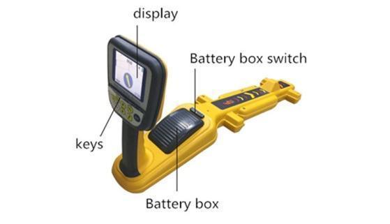 Receiver panel and function introduction
A receiver is an integration of a system circuit capable of
receiving a specific magnetic field and converting it into an
electrical signal to display it and prompt the operator. It is the
second core of this set of instruments. It is fully functional,
highly intelligent, portable, lightweight, and easy to operate.
Interface display content function introduction
Receiver Broad Peak Arrow Mode Interface
Frequency: Display the current receiving frequency value; the initial value
is 577Hz when power on.
Grating: The signal strength is indicated by the length of the grating; the
grating moves from both sides to the middle, and the signal is too
strong or out of range when the grating is full.
Three digits: the signal strength is indicated by the size of the number; the
valid range is 00.0-99.9, when 99.9 is displayed, the signal is too
strong or out of range.
Color compass: indicates the direction of the pipeline.
Depth & Current: Indicates the measured depth of the underground pipeline and the
current on the pipeline.
Gain: Indicates the magnification of the signal currently processed by
the receiver, with a dynamic range of 000-140db; it is
automatically adjusted by default. The initial boot is 60db.
Mode: Indicates the way the receiver receives the signal, and displays
narrow peak , wide peak , trough , broad peak arrow , peak + trough
and external equipment ; the initial power-on is wide peak.
External devices are automatically recognized.
Battery level: Indicates the current battery level; it is indicated by the
battery symbol.
Volume: Indicates the current working status of the buzzer, represented by
the horn symbol plus a line, one line is low loudness, two lines
are medium loudness, three lines are high loudness, and a cross is
to turn off the buzzer. The initial power-on is to turn off the
buzzer.
Left and Right Arrows: Arrows automatically appear off the cable to indicate the cable
location ; two arrows appear above the cable.
Current direction: When using the SS frequency, this function can display the
direction of the signal current to assist the operator in path
finding.
Phase Indication: When using the SS frequency, the receiver will display the phase
of the signal. Long press the frequency key to clear the phase.
Receiver characteristics
1) Cable positioning: Select the wave crest method and use parallel
antenna positioning to quickly track the target cable. When it is
above the cable, the signal is the largest and the two sides are
reduced. Choose the valley method and use the vertical antenna for
positioning. When there are no adjacent cables and interference
sources, the positioning is more accurate and reliable. When the
receiver is above the cable, the signal is the smallest and the
signal on both sides is large.
2) Depth measurement: In direct connection mode, the depth is
measured directly. Place the receiver directly above the pipeline,
and keep the instrument body still when the direction indicated by
the compass points straight ahead, and the real-time sounding value
is displayed in the upper left corner.
voice prompt
A great feature of this instrument is that it has a voice prompt,
which can reduce the operator's eye fatigue when working for a long
time, and make the detection work more simple and clear. The volume
of the sound emitted by the receiver is proportional to the
strength of the received signal. Under unity gain, when the sound
from the receiver is loud and rapid, it means that the received
signal is strong, and vice versa, it means that the
received signal is weak. When the receiver is in the crest method,
the sound is loudest and sharp right above the cable, and the sound
is small and sparse on both sides. When the receiver is in the
valley method, the sound is the smallest and most sparse right
above the pipeline, and the sound is loud and tight on both sides.Receiver working mode
working principle
When a signal is applied to the cable, there is a current on the
cable, and the current generates a magnetic field that radiates
around the cable. The frequency of the magnetic field is consistent
with the frequency of the applied signal. The strength is the cable
as the center of the circle and the radiation is decreased, and the
direction is the tangent direction of a certain point on the
radiation circle.
The receiver receives the magnetic field signal or the leaked
electric field signal radiated by the cable through the internal
antenna or external input device, and can be processed in two
different working modes, and the signal strength change is prompted
to the operator.
Signal reception mode - receiver working mode
Crest method (narrow peaks , broad peaks , broad arrows , peaks + valleys )
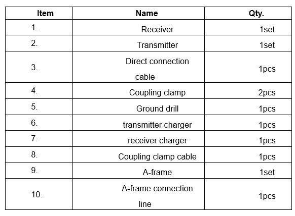
Trough method (trough )Packing list