| Sign In | Join Free | My frbiz.com |
|
| Sign In | Join Free | My frbiz.com |
|
| Categories | Rigid Stranding Machine |
|---|---|
| Brand Name: | Beyde |
| Model Number: | 500/12+18+24 |
| Place of Origin: | Hejian,China |
| MOQ: | 1 Set |
| Payment Terms: | L/C, T/T |
| Supply Ability: | 120 Set/Year |
| Delivery Time: | 120 Days after receive deposit |
| Packaging Details: | Container loading with safety packing |
| Warranty:: | 12 Months |
| PLC: | Siemens |
| Usage: | Stranding |
| Input wire: | 1.5-5.0mm |
| Max stranding: | 60mm |
| Max rotating: | 210r/min |
| Wrapping head: | option |
| Motor: | Siemens |
| Take-up: | 2000mm |
| Pay-off: | 1600mm |
| Capstan: | 1000-2500mm |
| Material: | Copper and aluminum conductor |
| Company Info. |
| Beyde Trading Co.,Ltd |
| Verified Supplier |
| View Contact Details |
| Product List |
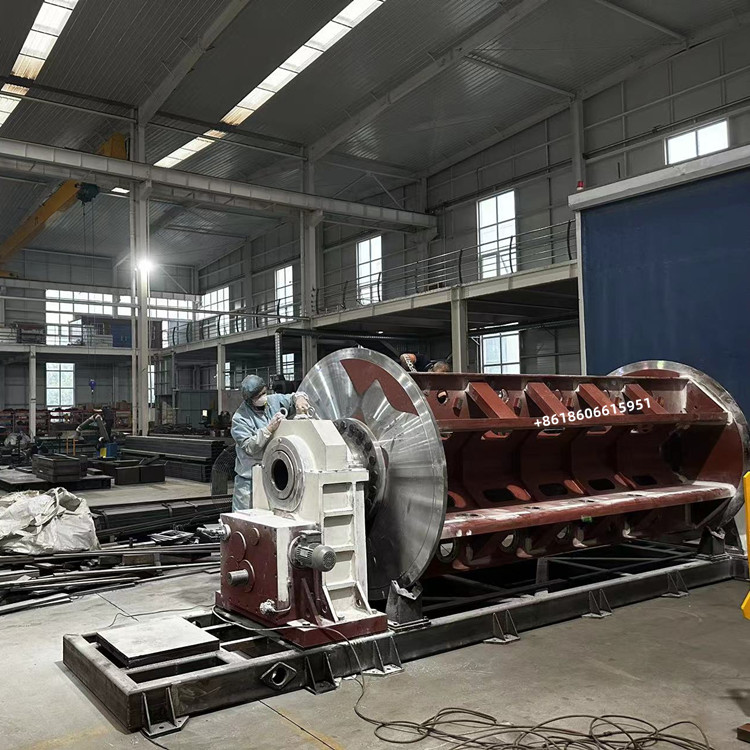
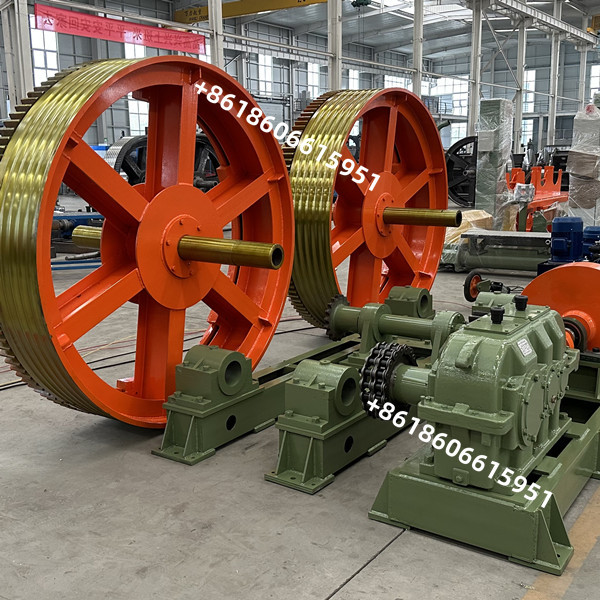
China Stranding Machine Exporter JLK-500/54 Large Production Capacity Machines
The machine is used for stranding copper, Aluminum. Stranding unilay and reverse concentric, round, compressed, compacted or sector shaped conductors to be used for the cable manufacturing or for the Over Head Conductors. Rigid stranding lines are ideal machine for making conductors of large size for LV/MV/HV power cables and over head conductors (AAC/AAAC/ACSR). Prepared for Bobbin Dia. 630mm to 710mm with automatic side or floor loading system at 45°as well as special systems adapted to customer need. Confuguration from 19 to 127 wire.
Contant tension control system and intelligent brake system:
By Tracking(Supersonic) the length of wire wrapped on bobbin, the length of wire remaining on bobbin will be detected and transmitted to PLC. The PLC will control the in-taking air by proportional valve and make the tension of wie constant following the length of wire remaining. Two groups controlling the tension of brake dics for paying-off to ensure the pressure on dics equal. Pneumatic brake system is controlled by intelligent brake system. When energency stop of machine, the speed signal of each cage will be trasmitted to PLC by sendsor. PLC will make calculation automatically and provide different brake force to each cage by proportional valve accordingly. Then the different cage will stop synchronized
| Machine Type | JLK- 500 | JLK - 630 | |
| Single wire dia. | 1.5-5.09(copper) 1.8-5.0(AL) | 1.5-5.0(copper) 1.8-5.0(AL) | |
| Max O.D | 45 | 45 | |
| Stranded pitch | 6 | 40-683 | 64-946 |
| 12 | 40-683 | 64-946 | |
| 18 | 46-780 | 46-780 | |
| 24 | 52-888 | 83-1226 | |
| Speed | 6 | 86-150 | 69-162 |
| 12 | 86-140 | 69-162 | |
| 18 | 75-135 | 61-143 | |
| 24 | 66-1455 | 53-125 | |
| Speed | 59 | 59 | |
| Bobbin | PND500 | PND630 | |
| Pay off bobbin | PN1600-PN2500 | PN1600-PN2500 | |
| Take up bobbin | PN2500 | PN2500-PN3150 | |
| Main motor | 75KW | 132KW | |
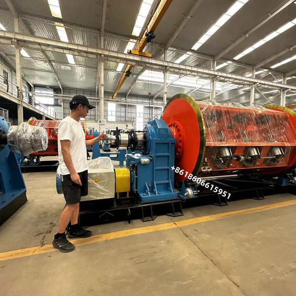
Main advantage of rigid stranding machine

5.2.1 Maximum speed of strand (full load)
6 discs 230r/min
12 disks 198r/min
18 disks 178r/min
24 plates 158r/min
5.2.2 Cage pitch (can be set on the touch screen)
6 discs infinitely adjustable
12 discs infinitely adjustable
18 discs infinitely adjustable
24 discs infinitely adjustable
5.2.3 Power of twisted body motor
6 plates 75kw (AC variable frequency motor)
12 trays 75KW (AC variable frequency motor)
18 trays 75KW (AC variable frequency motor)
24 trays 75KW (AC variable frequency motor)
5.2.4 Each section of the strand is driven by a separate AC motor
through a special gearbox, and can rotate left and right. The
gearbox has two high and low speed gears. The high gear is used
during normal stranding, and the slow gear is used when changing
the disc. The main motor drives the stranding body to rotate at a
slow speed, and the position of the upper disc is automatically
positioned using a handle switch.
5.2.5 Frame structure, the entire stranded body is double-supported
by the front and rear support frames, and the middle is supported
by a seamless steel pipe. The main steel plate connection surface
of the frame is processed and welded with high strength. The
overall frame after welding is annealed at high temperature in an
annealing furnace. The deformation and stress caused by the welding
of the steel plates are accelerated and aged. After 72 hours, it is
naturally cooled to the natural state. temperature, effectively
enhancing the strength of the entire frame. There is a machining
allowance for the brake surface of the strand body and a margin for
the top mounting hole. After all the holes are drilled and milled
in the gantry machining center, they are then finished on a
heavy-duty horizontal lathe. The bottom plate of the strand is made
of welded rectangular tubes. Compared with the ordinary channel
steel bottom plate, it effectively enhances the stability of the
strand and is more suitable for high-speed rotation of the strand.
Dynamic balancing test after assembly of the stranded body to
ensure stable high-speed operation.
5.2.6 The single-line pay-off tension is electronically detected
and electrically controlled, and adjusted by a pneumatic control
proportional valve imported from Japan to achieve constant
single-line pay-off tension from full to empty.
5.2.7 The wire reel adopts end-axis pneumatic clamping, and the
cylinder clamps the wire reel from bottom to top to facilitate the
up and down of the wire reel. After the wire reel is clamped, the
pneumatic interlocking mechanical safety locking mechanism realizes
linkage and stop retreat.
5.2.8 Using digital quantity to detect wire breakage can accurately
determine the wire breakage signal of any disk in each section of
the strand, and display which section or disk is broken on the
touch screen of the main console. The parking length for wire
breakage detection is 2M. Within (when the line speed is 20M/MIN),
the accuracy and accuracy of wire break detection are significantly
improved, ensuring detection accuracy.
5.2.9 The loading operation of each section of the stranding body
adopts the slow speed gear on the gear box. The main motor drives
the stranding body to rotate slowly for slow positioning. The
proximity switch is used to detect the positioning pulse signal to
ensure the loading of the stranding body. The location is accurate.
5.2.10 The surface of the tension plate is ground to ensure the
stability and balance of the tension.
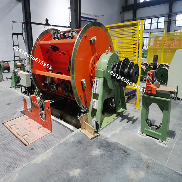
5.2.11 Each section of the strand adopts a wall-type protective
fence, which is fixed.
5.2.12 Each section of the strand is equipped with a hydraulic side
lower loading device.
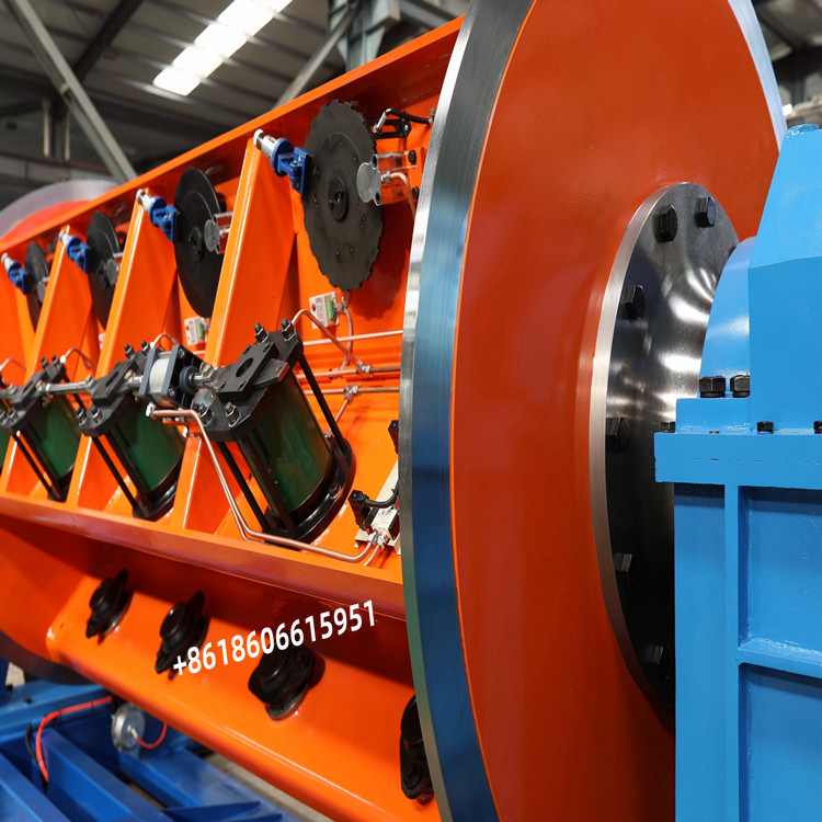
5.2.13 Each section of the stranded body is equipped with a set of
single-wire preforming devices. The single-wire preforming device
is used for stranding round single wires to ensure that the single
wires are not loose after the conductor section is disconnected
after stranding.
5.2.14 The single-section winching cage of this machine is equipped
with a central wire protection tube.
5.2 Lower side loading device
5.3.1 Applicable cable reel PND630mm
5.3.2 This loading device is an automatic loading device at the
bottom of the hydraulic drive side. It consists of an auxiliary
mechanism for the upper and lower disks, a chassis, a flipping
loading mechanism, a linear motion guide rail pair, and a hydraulic
system.
5.3.3 When the overturning upper plate mechanism is in the
horizontal position, the line reel is pushed into the fixed
position from the upper plate turntable, the hydraulic drive system
starts to work, and the piston rod of the winch-connected oil
cylinder stretches out (the line disc bracket and the piston rod
are winched. Continuous connection) drives the upper plate device
to perform a flipping motion with the fixed axis as the base point.
When flipped to the set angle, the bottom surface of the guide rail
hits the limit device on the bottom plate of the winch and stops
flipping. At this time, the piston rod continues to work, and the
drive wire reel bracket makes a linear motion along the guide rail
to the side upper disc to send the reel under the action of the
linear motion guide rail pair. When the wire reel reaches the
strand clamping position, the cylinder piston rod stops extending
under the action of the limit switch, and the strand clamping
device works to clamp the wire reel.
5.3.4 After the wire reel is installed, the oil cylinder piston
retracts, and the wire reel bracket moves linearly downward and
sideways along the guide rail. When the movement reaches the limit
at the bottom of the guide rail, the wire reel bracket stops
sliding, and the wire reel bracket and both sides The guide rails
are turned together along the fixed axis until the cylinder piston
retreats to the bottom and the wire reel bracket returns to the
horizontal position.
5.3.5 Features: Small footprint and easy maintenance. Easy to
operate and high efficiency. Strong integrity and clean working
conditions

|
