| Sign In | Join Free | My frbiz.com |
|
| Sign In | Join Free | My frbiz.com |
|
| Categories | Slurry Pump |
|---|---|
| Brand Name: | SHIZA |
| Model Number: | 6 / 4 D - |
| Certification: | ISO/CE |
| Place of Origin: | CHINA |
| MOQ: | 1 Set |
| Price: | Negotiable |
| Payment Terms: | T/T, Western Union |
| Supply Ability: | 300 Sets per Month |
| Delivery Time: | 7 Working Days |
| Packaging Details: | Plywood Crate |
| Material: | High Chrome Alloy A05,A49 |
| Usage: | Metallurgical,Coal |
| Fuel: | Diesel or Electric |
| Duty Type: | Heavy duty |
| Transmission Type: | CV/ZVZ/DCZ/CR |
| Power: | 60kw |
60 Kw High Concentration Centirfugal Sand Pump For Metallurgical,Coal
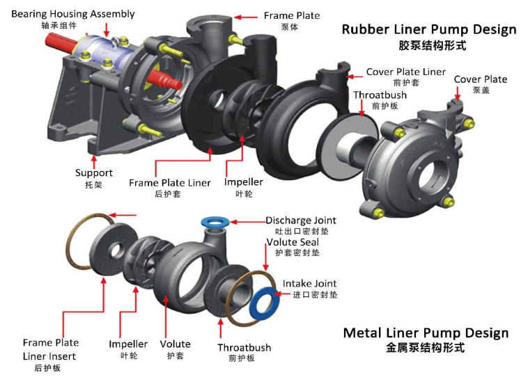
Main introduction of slurry pump
The basic structure of the 6 / 4 D - slurry pump is composed of six
parts: impeller, pump body, pump shaft, bearing, sealing ring and
stuffing box.
1. The impeller is the core part. It has a high speed and a large
force. The blades on the impeller play a major role. The impeller
must pass the static balance test before assembly. The inner and
outer surfaces of the impeller are required to be smooth to reduce
the frictional loss of water flow.
2, the pump body is also called the pump casing, it is the main
body of the pump. It acts as a support and is attached to the
bracket on which the bearing is mounted.
3. The function of the pump shaft is to connect the coupling to the
motor and transmit the torque of the motor to the impeller, so it
is the main component that transmits mechanical energy.
4. The bearing is a member that supports the pump shaft on the pump
shaft, and has two kinds of rolling bearings and sliding bearings.
Rolling bearings use butter as a lubricant to refuel properly.
Generally 2/3 ~ 3 / 4 of the volume will be too much heat, too
little and there is noise and heat! The plain bearing uses a
transparent oil as a lubricant and refuels to the oil line. Too
much oil will ooze along the pump shaft and float, too few bearings
will overheat and burn out! During the operation of the pump, the
temperature of the bearing is at most 85 degrees and generally runs
at about 60 degrees. If it is high, it is necessary to find the
cause (whether there are impurities, whether the oil is black or
not, whether it is water) and deal with it in time!
5, the seal ring is also known as the leak reduction ring. The gap
between the impeller inlet and the pump casing is too large, so
that the water in the high pressure zone of the pump flows to the
low pressure zone through the gap, which affects the water output
of the slurry pump and reduces the efficiency! Too small a gap will
cause friction between the impeller and the pump casing. In order
to increase the backflow resistance and reduce the internal
leakage, and delay the service life of the impeller and the pump
casing, a sealing ring is installed at the inner edge of the pump
casing and the outer joint of the impeller, and the sealing gap is
preferably maintained between 0.25 and 1.10 mm.
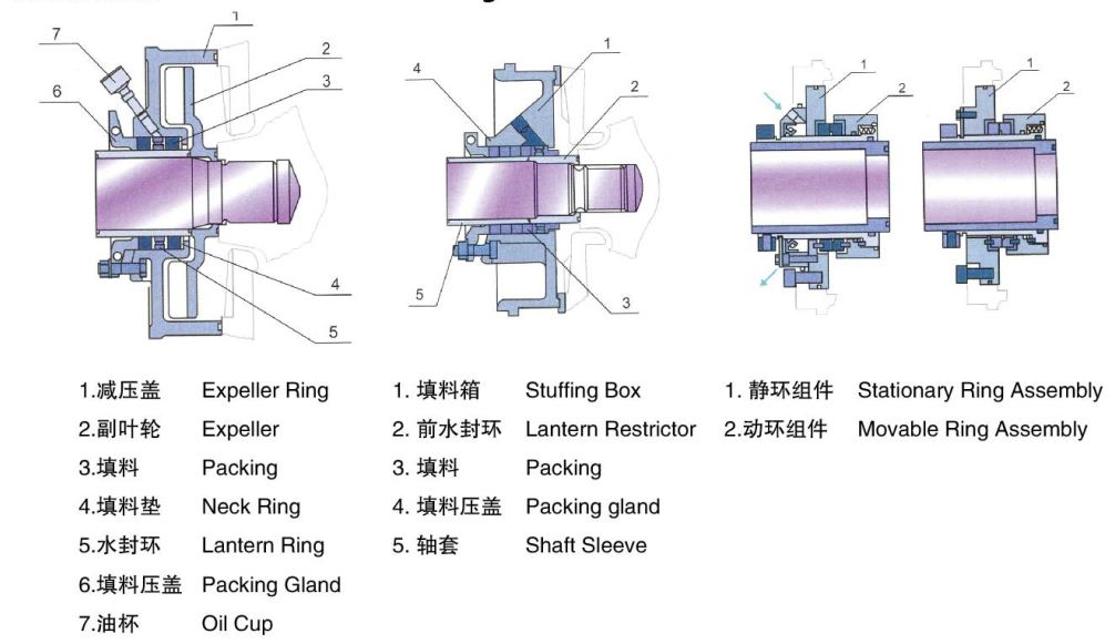
6. The stuffing box is mainly composed of packing, water sealing
ring, packing tube, packing gland and water sealing tube. The
function of the stuffing box is mainly to close the gap between the
pump casing and the pump shaft, so that the water flow in the pump
does not flow to the outside and the outside air does not enter the
pump. Always keep the vacuum inside the pump! When the pump shaft
and the packing friction generate heat, the water seals the water
to the water seal ring to cool the packing! Keep the pump running
properly. Therefore, it is especially important to check the
stuffing box during the running inspection of the pump! The packing
should be replaced after about 600 hours of operation.
Model meaning
6 / 4 D - (R)
6------------Suction diameter(Inch)
4------------Discharge diameter(Inch)
D------------Support type
---------- Pump Model
R-------------Natural Rubber
Specifications
| Pump Model | 6 / 4 D - |
| Allowable Max.Power | 60 kw |
| Capacity | 162 - 360 m³/h |
| Head | 12 - 56 m |
| Speed | 800 - 1550 r/min |
| Meax.Eff. | 65% |
| NPSH | 5 - 8 m |
| Impeller Diameter | 365 mm |
Features
1). Cantilever, horizontal Slurry discharging pump
2). Excellent hydraulic performance, high efficiency, and low wear rate
3). Better wear-resistance and corrosive resistance
4). Frame plate for type pumps have replaceable wear-resistant metal liners or rubber liners. The impellers are made of wear-resistant metal or rubber
5). In allowable pressure range, it can be used in series in stages, and allowable maximum working pressure is 3.6Mpa.
6). Centrifugal seal, mechanical seal and packing seal are available .
7). The discharge branch can be positioned at interval of 45 degrees by request and oriented to any eight positions to suit installations and applications.
Typical Applications:
Ash Handling
Cyclone Feeds
Pulp and Paper
Abrasive Slurries
Coal Preparation
Mineral Processing
Aggregate Processing
Installation:
The quality of the pump installation has an important impact on the
operation and life of the pump, so installation and calibration
must be done carefully. The shape and installation dimensions of
the pump.
1. Installation and calibration:
1) Remove greasy and dirt from the base and place the base on the
foundation.
2) Check the level of the base with a spirit level, allowing the
wedge to be leveled.
3) Water the base and anchor bolt holes with cement.
4) After the cement is dry, check whether the holes of the base and
anchor bolts are loose. After proper fitting, tighten the anchor
bolts and check the level.
5) Clean the support plane of the base, the pump foot and the plane
of the motor foot, and install the water recording and motor on the
base.
6) A certain gap should be maintained between the couplings. Check
whether the center line of the pump shaft and the motor shaft are
consistent. Use a thin gasket to adjust it to be concentric.
Measuring the outer and outer sides of the coupling, the difference
between the left and right shall not exceed 0.1 mm, and the maximum
and minimum difference between the end faces of the two couplings
shall not exceed 0.3 (mm).
2, installation instructions:
1) The installation height of the pump, the length of the pipeline,
the diameter and the flow rate should be calculated in accordance
with the calculation, and strive to reduce unnecessary losses.
2) When transporting long distances, take a larger diameter. The
pipeline of the pump should have its own support. The weight of the
unsupported pipeline should be added to the pump to avoid crushing
the pump.
3) If the discharge line is installed with a check valve, it should
be installed outside the gate valve.
Construction Design
Shaft Seal Module Design
Performance table
| MODEL | ALLOWABLE MATING | MATERIAL | CLEAN WATER PERFORANCE | IMPELLER | |||||||
| MAX.POWER | LINER | IMPELLER | Q Capacity | H Head | Speed | Max. Eff. | NPSH | VANES NO. | IMPELLER DIA | ||
| (KW) | m3/h | L/s | (m) | n(r/min) | (%) | (m) | (mm) | ||||
| 1.5/B- | 15 | M | M | 12.6-28.8 | 3.5-8 | 6-68 | 1200-3800 | 40 | 2--4 | 5 | 152 |
| RU | RU | 10.8-25.2 | 3--7 | 7-52 | 1400-3400 | 30 | 3 | ||||
| 1/1.5B- | 15 | M | M | 16.2-34.2 | 4.5-9.5 | 25-92 | 1400-2200 | 20 | 2-5.5 | 5 | 330 |
| 2/1.5B- | 15 | M | M | 32.4-72 | 9--20 | 6-58 | 1200-3200 | 45 | 3.5-8 | 5 | 184 |
| RU | RU | 25.2-54 | 7--15 | 5.5--41 | 1000-2600 | 50 | 2.5-5 | 5 | 178 | ||
| 3/2C- | 30 | M | M | 39.6-86.4 | 11--24 | 12-64 | 1300-2700 | 55 | 4--6 | 5 | 214 |
| RU | RU | 36-75.6 | 10--21 | 13-46 | 1300-2300 | 60 | 2--4 | 5 | 213 | ||
| 3/2D-HH | 60 | M | M | 68.4-136.8 | 19-38 | 25-87 | 850-1400 | 47 | 3-7.5 | 5 | 457 |
| 4/3C- | 30 | M | M | 86.4-198 | 24-55 | 9-52 | 1000-2200 | 71 | 4--6 | 5 | 245 |
| RU | RU | 79.2-180 | 22-50 | 5-34.5 | 800-1800 | 59 | 3--5 | ||||
| 4/3E-HH | 120 | M | M | 126-252 | 35-70 | 12-97 | 600-1400 | 50 | 2--5 | 5 | 508 |
| 6/D- | 60 | M | M | 162-360 | 40-100 | 12-56 | 800-1550 | 65 | 5--8 | 5 | 365 |
| RU | RU | 144-324 | 40-90 | 12-45 | 800-1350 | 65 | 3--5 | 5 | 365 | ||
| 6/4S-HH | 560 | M | M | 324-720 | 90-200 | 30-118 | 600-1000 | 64 | 3--8 | 5 | 711 |
| 6S-HH | 560 | M | M | 468-1008 | 130-280 | 20-94 | 500-1000 | 65 | 4--12 | 5 | 711 |
| 8/6E- | 300 | M | M | 360-828 | 100-230 | 10-61 | 500-1140 | 72 | 2--9 | 5 | 510 |
| RU | RU | 324-720 | 90-200 | 7-49 | 400-1000 | 65 | 5--10 | 5 | 510 | ||
| 10/8E-M | 120 | M | M | 666-1440 | 185-400 | 14-60 | 600-1100 | 73 | 4--10 | 5 | 549 |
| 10/8ST- | 560 | M | M | 612-1368 | 170-380 | 11-61 | 400-850 | 71 | 4--10 | 5 | 686 |
| RU | RU | 540-1118 | 150-330 | 12-50 | 400-750 | 75 | 4--12 | ||||
| 12/10ST- | 560 | M | M | 936-1980 | 260-550 | 7-68 | 300-800 | 82 | 6 | 5 | 762 |
| RU | RU | 720-1620 | 200-450 | 7-45 | 300-650 | 80 | 2.5-7.5 | ||||
| 14/12ST- | 560 | M | M | 1260-2772 | 350-770 | 13-63 | 300-600 | 77 | 3--08 | 5 | 965 |
| RU | RU | 1152-2520 | 320-700 | 13-44 | 300-500 | 79 | 3--10 | ||||
| 16/14TU- | 1200 | M | M | 1368-3060 | 380-850 | 11-63 | 250-550 | 79 | 4--10 | 5 | 1067 |
| 20/18TU- | 1200 | M | M | 2520-5400 | 700-1500 | 13-57 | 200-400 | 85 | 5--10 | 5 | 1370 |

|
