Main Characteristics:
B1) Supply voltage AC: 220V, 110V, 24V, 12V
B2) Supply voltage DC: 24V, 12V
B3) Sensitivity: adjustable in 3 increments (high .medium. low)
B4) Storage temperature: -40°C to +85°C
B5) Reaction time: 100ms
B6) Loop connection wiring: Maximum length 200 meters,
B7) Twisted at least 20 times per meter
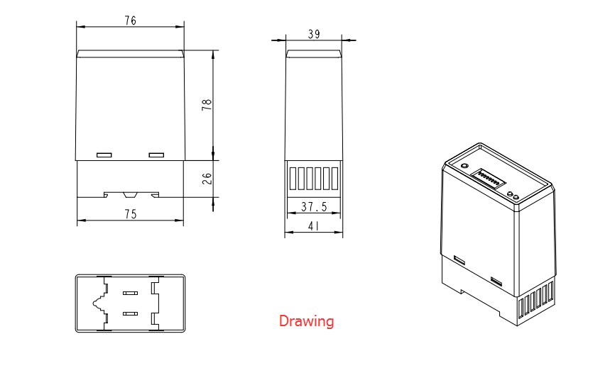
B8) Net Weight: 300g
Install Detector :
The detector must be installed in a convenient weatherproof
location as close to the loop as possible. Installation location
must choose to stay away from the heat source, it around other
devices must maintain a distance of at least 10mm (mustn’t fix
cling to the cabinet). A correct loop configuration and detector
installation will ensure a successful inductive loop detection
system. Loop of several important parameters include: loop figure,
size, and turns, install methods (details as “Loop installation
guide”).
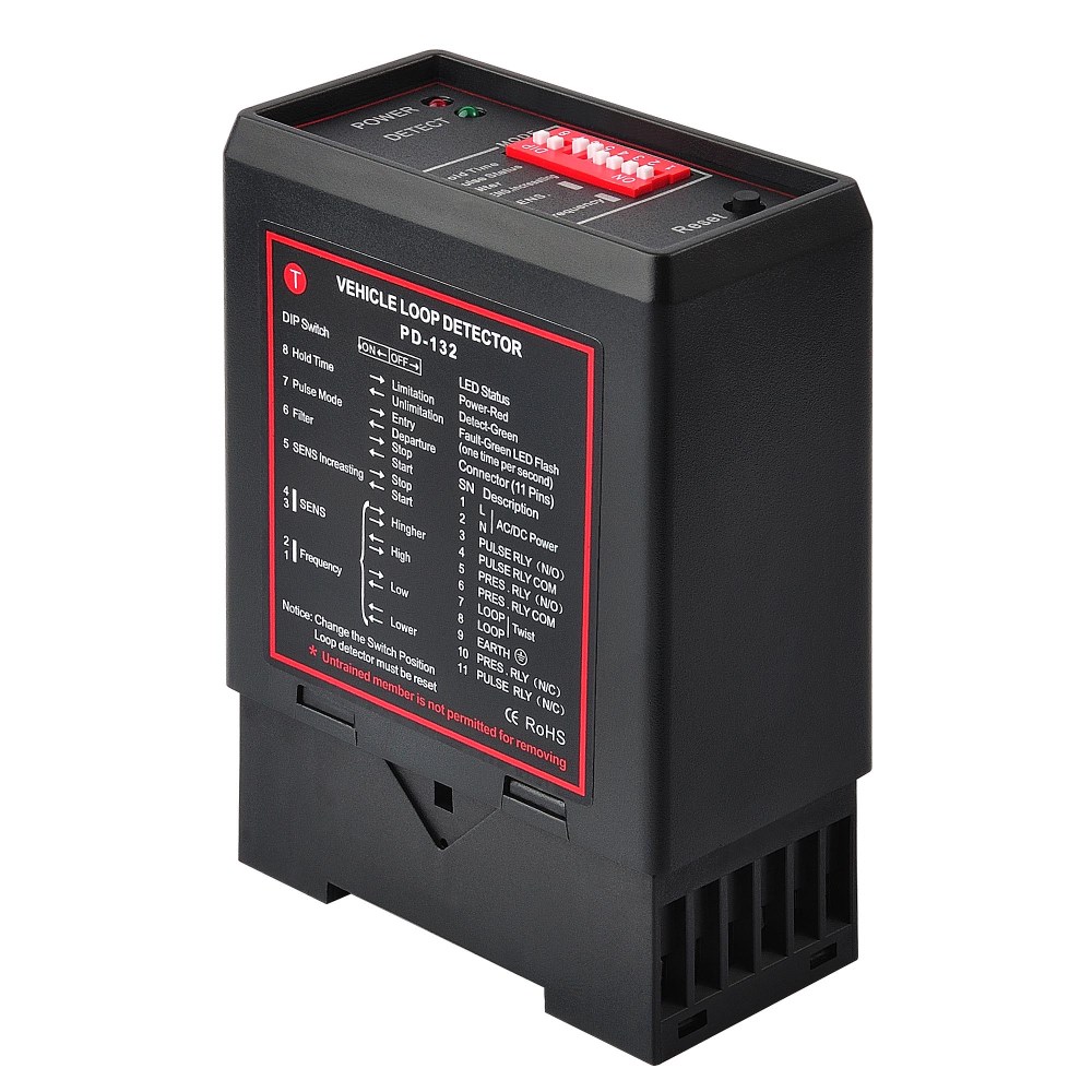
Operation and Indication
Whenthe power is applied, the red Power LED will glow and the
detector is tuning,the green Check LED blink about 3 seconds. The
green LED will also glow whenever a vehicle is detected passing
over the inductive loop. If a loop fault
exists the green LED will come on and flash indicating a fault.
Loopno connected: Loop too small:
Looptoo large:
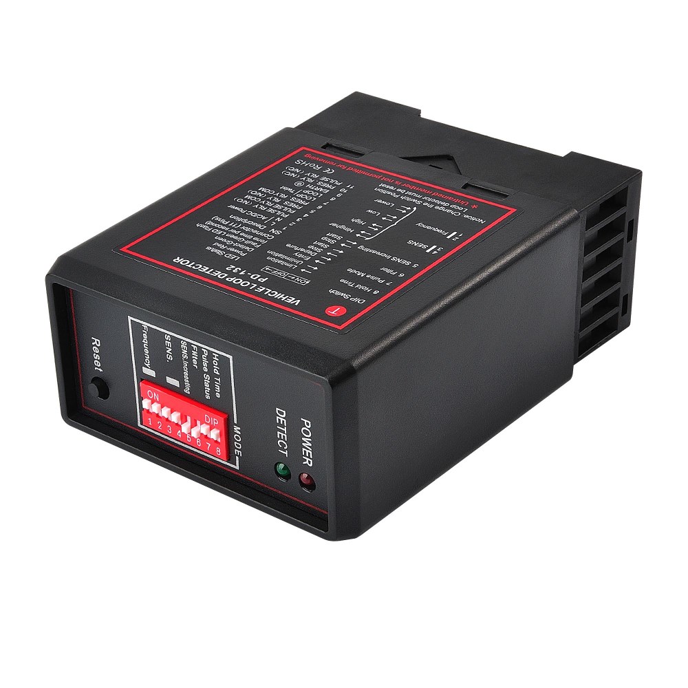
Frequency
Thefrequency can be set by the two DIP switch on the circuit board.
Disconnect power and then take down the detector from the socket,
remove the shell. DIP6 (LA) is used for setting the frequency. ON:
working in low frequency. OFF:working in high frequency The
detector will be calibrated automatically when connecting the power
after adjusting the frequency. Notice: High frequency has been set.
The installation distance is too close between the two loop
detectors, the different frequency can be setting by the
user.Sensitivity The response sensitivity can be set using the
threestage switch on the front. The setting L corresponds to the
lowest sensitivity. M is the medium sensitivity and H is the
highest sensitivity. After the sensitivity has been set, a reset
and a calibration automatically takes place.
Attention If thedetector isn’t working normally, you must check the
loop and wiring at first, and then alter the frequency or the
sensitivity.
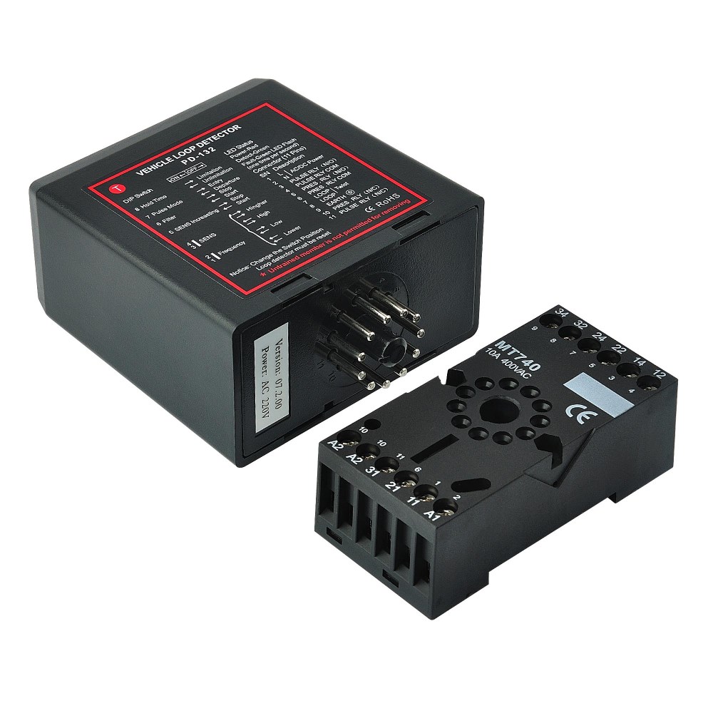
Output Relay
Whenvehicle press loop, the relay's output mode set by the main
control panel switch. TLD-410 has two loops, corresponding to two
output relays. loop1 (7-8 pin) corresponds to the relay 1 (5, 6, 10
pin) output for the existence of a fixed output signal, the loop 2
(7,9 pin) corresponds to the relay 2 (3,4,11 pin) and pull the
output signal from the DIP code switch DIP1, DIP2, DIP3 (SW0,SW1,
SW2) decision.ListenRead phonetically.Vehiclepresence check model
output setting Vehicle direction (count) check mode output signal
and setting:
Reset
Thedetector automatically reset and tune to the inductive loop when
the power is applied, whether on initial installation or after any
break in power supply.Should it be necessary to retune the
detector, as may be required after
changing any of the switches or after moving the detector from one
installation to another.
A.Application Scope :
A1)Parking lot entrances vehicle detection ;
A2)Parking lot space information acquisition system ;
A3)Electronic police traffic lights snap shot system ;
A4)Traffic monitoring system .

