| Sign In | Join Free | My frbiz.com |
|
| Sign In | Join Free | My frbiz.com |
|
| Categories | Optical Transceiver Module |
|---|---|
| Brand Name: | TAKFLY |
| Model Number: | TK-Bxx92-3LCD60 |
| Certification: | CE,ROHS,REACH,ISO9001,ISO14001 |
| Place of Origin: | Guangdong, SHENZHEN |
| MOQ: | 1 Pices |
| Price: | US$0.01 ~ US$1200/PC |
| Payment Terms: | L/C, D/A, D/P, T/T, Western Union, MoneyGram |
| Delivery Time: | 3-7working days |
| Ratio: | 50/50 |
| Center Wavelength: | 1450nm |
| Insertion Loss: | ≤0.3dB |
| Package Weight: | 10g |
| Package Type: | Bare Fiber, 900um Loose Tube, 2mm Cable |
| Wavelegth: | 1310nm |
| Axis Alignment: | Slow axis or Fast axis |
| Wavelength Range: | 1310nm, 1550nm |
| Application: | Optical Communication Systems |
| Splitter Ratio: | 98/2 |
| Storage Temperature: | -40~+85℃ |
| Port Number: | 1x2 |
| Fiber Length: | 1m |
| Fiber: | PM Corning 980nm fiber |
| Power Handling Capacity: | High Power |
| Company Info. |
| TAKFLY COMMUNICATIONS CO., LTD. |
| Verified Supplier |
| View Contact Details |
| Product List |
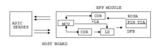
The transceiver module comprises a transmitter with a 1270/ 1330nm DFB laser transmitter and the receiver section consists of a APD photodiode integrated with a TIA Transmitter and receiver are separate within a wide temperature range of 0℃ to +70℃ and offers optimum heat dissipation and excellent electromagnetic shielding thus enabling high port densities for 10GbE systems.
Features
Maximum link length of 60KM with SMF
1270/ 1330nm DFB laser Transmitter and 1330/ 1270nm Receiver
XFP MSA package with LC connector
No reference clock required
Loop Back Support.
+3.3V ,+1.8V power supply
Power dissipation <2W
Compatible with RoHS
Built-in digital diagnostic functions
Temperature range 0°C to 70°C
Applications
Absolute Maximum Ratings
| Parameter | Symbol | Min. | Typ. | Max. | Unit | Note |
| Storage Temperature | Ts | -40 | - | 85 | ºC | |
| Storage Ambient Humidity | HA | 5 | - | 95 | % | |
| Operating Relative Humidity | RH | - | - | 85 | % | |
| Power Supply Voltage | VCC | -0.3 | - | 4 | V | |
| Signal Input Voltage | VCC | Vcc-0.3 | - | Vcc+0.3 | V |
Recommended Operating Conditions
| Parameter | Symbol | Min. | Typ. | Max. | Unit | Note |
| Ambient Operating Temperature | TA | 0 | - | 70 | ºC | Without air flow |
| Power Supply Voltage | VCC | 3.14 | 3.3 | 3.47 | V | |
| Power Supply Current | ICC | - | - | 450 | mA | |
| Data Rate | BR | 10.3125 | Gbps | |||
| Transmission Distance | TD | 2 | - | 60 | km | Note (1) |
| Coupled fiber | Single mode fiber | ITU-T G.652 | ||||
Specification of Transmitter
| Parameter | Symbol | Min. | Typ. | Max. | Unit | Note |
| Average Launched Power | PO | 2 | - | 6 | dBm | |
| Average Launched Power(Laser Off) | POUT-OF F | - | - | -30 | dBm | Note (1) |
| Optical Modulation Amplitude | OMA | -3 | - | - | dBm | Note (1) |
| Center Wavelength Range | λC | 1270/1330 | nm | |||
| Side mode suppression ratio | SMSR | 30 | - | - | dB | |
| Spectrum Bandwidth(-20dB) | σ | - | - | 1 | nm | |
| Extinction Ratio | ER | 3.5 | 6 | - | dB | Note (2) |
| Output Eye Mask | Compliant with FC_PI_4 REV 7.0 | Note (2) | ||||
1) The optical power is launched into SMF
2) Measured with RPBS 2^31-1 test pattern @10.3125Gbs
Specification of Receiver
| Parameter | Symbol | Min. | Typ. | Max. | Unit | Note |
| Input Optical Wavelength | λIN | 1330/1270 | nm | |||
| Receiver Sensitivity in average | PIN | - | - | -20 | dBm | Note (1) |
| Input Saturation Power (Overload) | PSAT | 0.5 | - | - | dBm | Note (1) |
| LOS Assert | PA | -30 | - | - | dBm | |
| LOS De-Assert | PD | - | - | -25 | dBm | |
| LOS -Hysteresis | PHys | 0.5 | - | 4 | dB |
1) Measured with RPBS 2^31-1 test pattern @10.3125Gbs BER=<10^-12 ER=6DB
Electrical Interface Characteristics
| Parameter | Symbol | Min. | Typ. | Max. | Unit | Note |
| Total power supply current | Icc | - | - | 350 | mA | |
| Transmitter | ||||||
| Differential Data Input Voltage | VDT | 120 | - | 820 | mVp-p | |
| Differential line input Impedance | RIN | 85 | 100 | 115 | Ohm | |
| Transmitter Fault Output-High | VFaultH | 2.4 | - | Vcc | V | |
| Transmitter Fault Output-Low | VFaultL | -0.3 | - | 0.8 | V | |
| Transmitter Disable Voltage- High | VDisH | 2 | - | Vcc+0.3 | V | |
| Transmitter Disable Voltage- low | VDisL | -0.3 | - | 0.8 | V | |
| Receiver | ||||||
| Differential Data Output Voltage | VDR | 300 | - | 850 | mVp-p | |
| Differential line Output Impedance | ROUT | 80 | 100 | 120 | Ohm | |
| Receiver LOS Pull up Resistor | RLOS | 4.7 | - | 10 | KOhm | |
| Data Output Rise/Fall time | tr/tf | 20 | - | - | ps | |
| LOS Output Voltage-High | VLOSH | 2 | - | Vcc | V | |
| LOS Output Voltage-Low | VLOSL | -0.3 | - | 0.4 | V | |
Pin Description
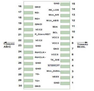
Pin | Logic | Symbol | Name/Description | Note |
| 1 | GND | Module Ground | 1 | |
| 2 | VEE5 | Optional –5.2 Power Supply – Not required | ||
| 3 | LVTTL-I | Mod-Desel | Module De-select; When held low allows the module to respond to 2-wire serial interface commands | |
| 4 | LVTTL-O | Interrupt | Interrupt (bar); Indicates presence of an important condition which can be read over the serial 2-wire interface | 2 |
| 5 | LVTTL-I | TX_DIS | Transmitter Disable; Transmitter laser source turned off | |
| 6 | VCC5 | +5 Power Supply | ||
| 7 | GND | Module Ground | 1 | |
| 8 | VCC3 | +3.3V Power Supply | ||
| 9 | VCC3 | +3.3V Power Supply | ||
| 10 | LVTTL-I | SCL | Serial 2-wire interface clock | 2 |
| 11 | LVTTLI/O | SDA | Serial 2-wire interface data line | 2 |
| 12 | LVTTL-O | Mod_Abs | Module Absent; Indicates module is not present. Grounded in the module. | 2 |
| 13 | LVTTL-O | Mod_NR | Module Not Ready; XGIGA defines it as a logical OR between RX_LOS and Loss of Lock in TX/RX. | 2 |
| 14 | LVTTL-O | RX_LOS | Receiver Loss of Signal indicator | 2 |
| 15 | GND | Module Ground | 1 | |
| 16 | GND | Module Ground | 1 | |
| 17 | CML-O | RD- | Receiver inverted data output | |
| 18 | CML-O | RD+ | Receiver non-inverted data output | |
| 19 | GND | Module Ground | 1 | |
| 20 | VCC2 | +1.8V Power Supply – Not required | ||
21 | LVTTL-I | P_Down/RST | Power Down; When high, places the module in the low power stand-by mode and on the falling edge of P_Down initiates a module reset | |
| Reset; The falling edge initiates a complete reset of the module including the 2-wire serial interface, equivalent to a power cycle. | ||||
| 22 | VCC2 | +1.8V Power Supply – Not required | ||
| 23 | GND | Module Ground | 1 | |
| 24 | PECL-I | RefCLK+ | Reference Clock non-inverted input, AC coupled on the host board – Not required | 3 |
| 25 | PECL-I | RefCLK- | Reference Clock inverted input, AC coupled on the host board – Not required | 3 |
| 26 | GND | Module Ground | 1 | |
| 27 | GND | Module Ground | 1 | |
| 28 | CML-I | TD- | Transmitter inverted data input | |
| 29 | CML-I | TD+ | Transmitter non-inverted data input | |
| 30 | GND | Module Ground | 1 |
Notes:
1) Module circuit ground is isolated from module chassis ground within the module.
2) Open collector; should be pulled up with 4.7k – 10kohms on host board to a voltage between 3. 15V and 3.6V.
3) A Reference Clock input is not required by the XFP-10GER. If present, it will be ignored.
Recommended Block Circuit
Outline Dimensions

Regulatory Compliance
| Feature | Reference | Performance |
| Electrostatic discharge (ESD) | IEC/EN 61000-4-2 | Compatible with standards |
| Electromagnetic Interference (EMI) | FCC Part 15 Class B EN 55022 Class B (CISPR 22A) | Compatible with standards |
| Laser Eye Safety | FDA 21CFR 1040.10, 1040.11 IEC/EN 60825-1, 2 | Class 1 laser product |
| Component Recognition | IEC/EN 60950, UL | Compatible with standards |
| ROHS | 2002/95/EC | Compatible with standards |
| EMC | EN61000-3 | Compatible with standards |

|
